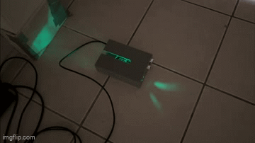
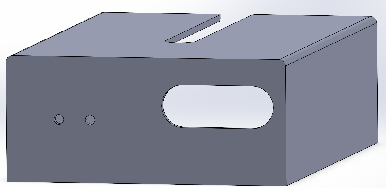
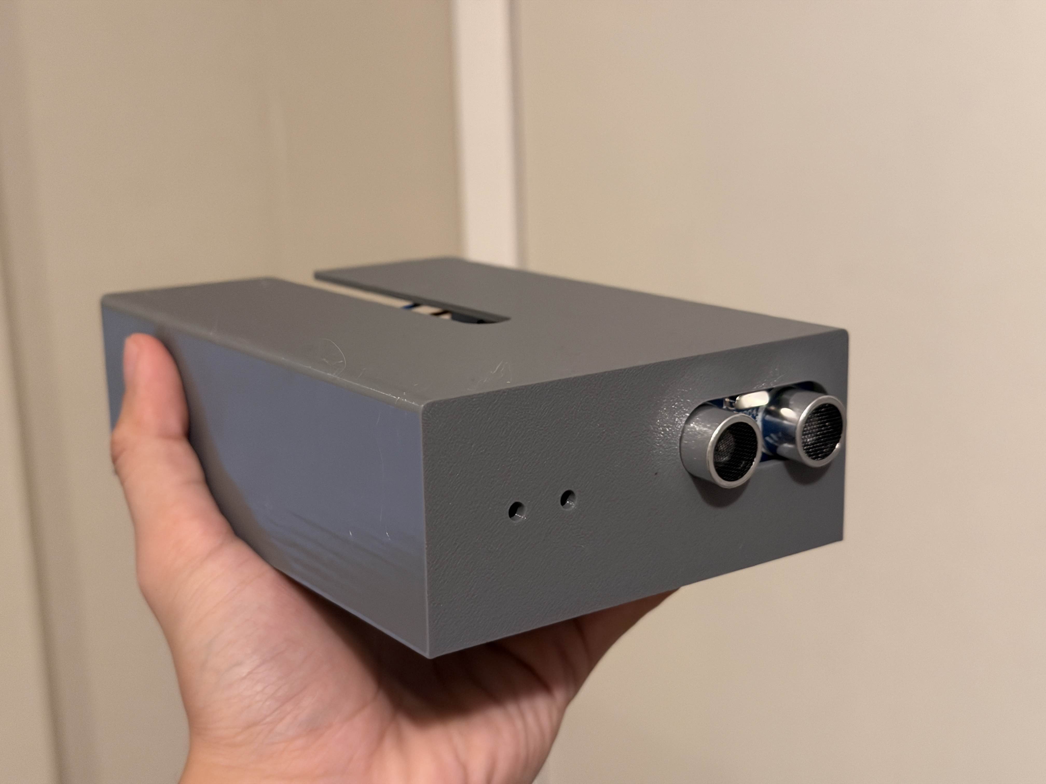
This is what the Doorbell device looks like while on, with the lights and buzzer (not audible) both running.
This is what the Doorbell device looks like while on, with the lights and buzzer (not audible) both running.
For my final project in HCDE 439, I designed and built an alarm device called Doorbell. This device is designed to recognize movement by using an ultrasonic sensor which can detect changes in distance, and then triggers a toggleable alarm and light response. The alerts can be toggled by pressing the "M" key on the connected computer. I started this project as a basic alarm device, and realized that it could theoretically be used for various applications that need me to be aware of motion or changing distances.
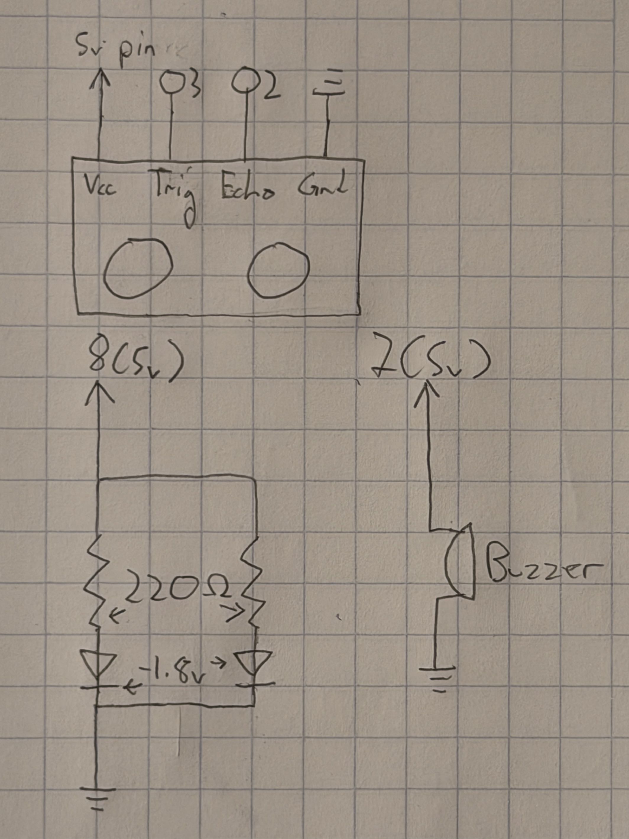 This diagram represents the device's circuitry. The ultrasonic sensor is connected to
digital pins to send data to the Arduino, which in turn controls the alarm lights
and buzzer. The green LEDs are controlled by a digital output which turns on or off,
and have an ideal maximum current of ~20 mA. Using Ohm's law to calculate an ideal
resistance gets the following value:
This diagram represents the device's circuitry. The ultrasonic sensor is connected to
digital pins to send data to the Arduino, which in turn controls the alarm lights
and buzzer. The green LEDs are controlled by a digital output which turns on or off,
and have an ideal maximum current of ~20 mA. Using Ohm's law to calculate an ideal
resistance gets the following value: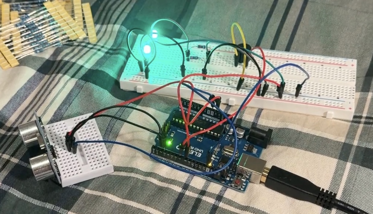
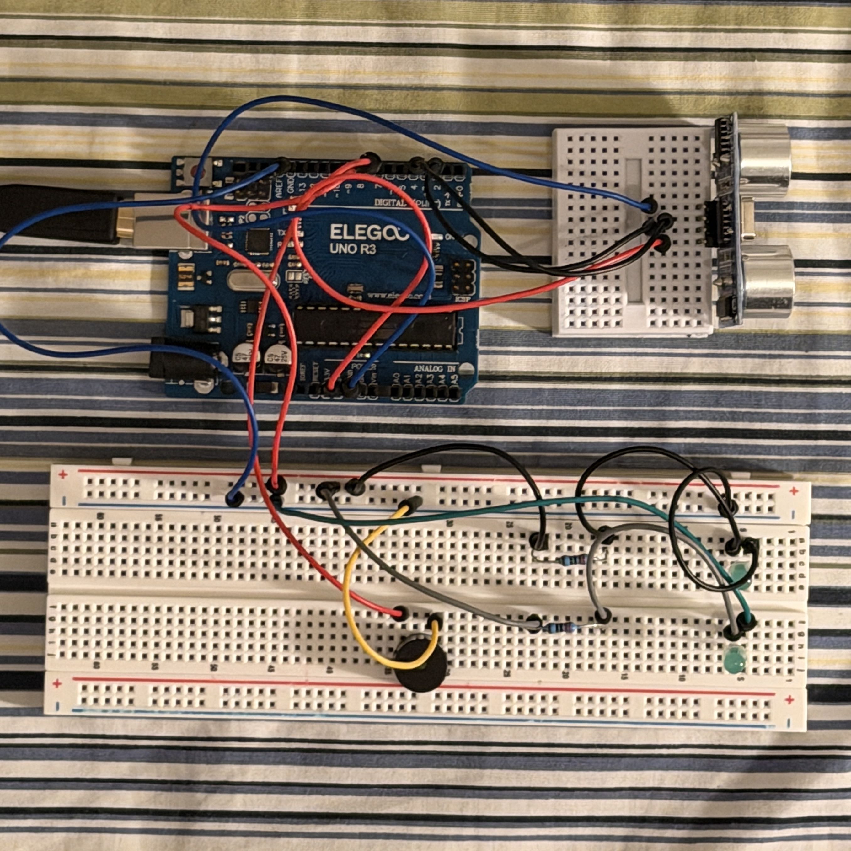
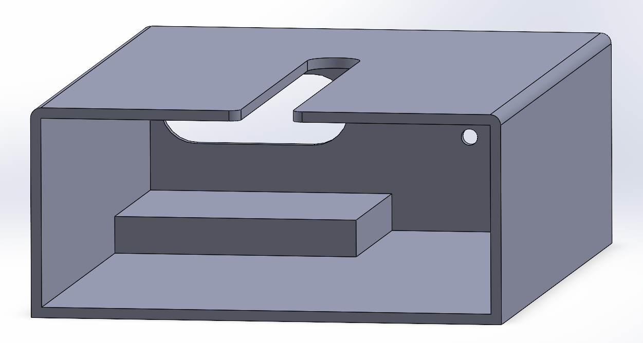
 This is what the printed device looks like with the components inside.
Most of the functionality for my device was implemented in code on the Arduino, which is responsible for controlling the sensor and LEDs. I added computer control as a way to control the alarm function. When the device is first set up, it enters a short calibration period where it saves the nearest detected distance and uses that as the reference "alarm distance". Afterwards, if anything comes closer than the alarm distance, the device will trigger its buzzer and LEDs. At the same time, if the mute key on the keyboard is pressed, that will toggle the functioning of the LEDs and buzzer altogether.
    const int xPin = A1; // Identifies the X-axis pin
    const int yPin = A0; // Identifies the Y-axis pin
    const int ledPin = 8; // Identifies the blue LED pin
    const int buzzer = 7; // Identifies the buzzer pin
    const int trig = 2; // Identifies the sensor "trig" pin
    const int echo = 3; // Identifies the sensor "echo" pin
    bool mute = true; // Creates a variable for "muting" the system
    bool manualMute = false; // Creates a variable for manual mute control
    int triggerDist = 0; // Initialize the trigger distance at 0 in

    void setup() { // Setup
        Serial.begin(9600); // Sets baud rate for serial usage
        pinMode(ledPin, OUTPUT); // Sets the blue LED pin for output
        pinMode(buzzer, OUTPUT); // Sets the buzzer pin for output
        pinMode(trig, OUTPUT); // Sets the trig pin for output (sending signals)
        pinMode(echo, INPUT); // Sets the echo pin for input (receiving signals)
        delay(200); // Wait 200ms for sensors
        while(millis() < 3000) { // 3-second calibration period
            digitalWrite(trig, LOW); // Deactivate the sensor
            delay(5); // Wait 5 ms
            digitalWrite(trig, HIGH); // Send a ping
            delay(5); // Wait 5 ms
            digitalWrite(trig, LOW); // Deactivate the sensor
            long calibDuration, calibInches; // Set up calibration measurement units
            calibDuration = pulseIn(echo, HIGH); // Measure the sensor ping
            calibInches = calibDuration / 74 / 2; // Convert the duration to a distance in inches
            if (calibInches > triggerDist) { // If current distance is larger than trigger distance
                triggerDist = calibInches; // Set trigger distance to current
            }
        }
        triggerDist--; // Set trigger distance to measured - 1 inch
    }

    void loop() { // Main loop
        if (Serial.available() > 0) { // If there is serial output
            int inByte = Serial.read(); // Reads from the port
            if (inByte == 1) { // If "1" is received
                manualMute = !manualMute; // Toggle manual mute control
            }
        }
        if (mute) { // If mute is true
            digitalWrite(buzzer, LOW); // Set buzzer to low
            digitalWrite(ledPin, LOW); // Set LED to high
            digitalWrite(trig, LOW); // Deactivate the sensor
            delay(5); // Wait 5 ms
            digitalWrite(trig, HIGH); // Send a ping
            delay(5); // Wait 5 ms
            digitalWrite(trig, LOW); // Deactivate the sensor
            long duration, inches; // Setup distance measurements
            duration = pulseIn(echo, HIGH); // Measure the sensor ping
            inches = duration / 74 / 2; // Convert the duration to a distance in inches
            if (!manualMute) { // If manual mute control is off
                if (inches < triggerDist) { // If the distance is less than the trigger range
                    mute = false; // Sets mute to false
                } else { // If the distance is outside the trigger range
                    mute = true; // Sets mute to true
                }
            }
            Serial.println(1); // Prints to serial
            delay(50); // Wait 50 ms
        } else { // If mute is false
            Serial.println(2); // Prints new output to serial
            digitalWrite(buzzer, LOW); // Sets buzzer to low
            digitalWrite(ledPin, LOW); // Sets LEDs to low
            delay(100); // Waits 100 ms
            digitalWrite(ledPin, HIGH); // Sets LEDs to high
            delay(100); // Waits 100 ms
            digitalWrite(buzzer, HIGH); // Sets buzzer to high
            digitalWrite(ledPin, LOW); // Sets LEDs to low
            delay(100); // Waits 100 ms
            digitalWrite(ledPin, HIGH); // Sets LEDs to high
            delay(100); // Waits 100 ms
            if (manualMute) { // If manualMute is true
                mute = true; // Set mute to true
            } else { // If manualMute is not true
                mute = false; // Set mute to false
            }
        }
    }
    // Final project for HCDE 439 AUT 25
    // This code is partly based on the in-class p5.js demos
    const BAUD_RATE = 9600; // Sets up baud rate for serial usage
    let port, connectBtn, elementSize; // Declare global variables

    // Sets up the canvas
    function setup() {
        setupSerial(); // Runs the serial setup function
        createCanvas(windowWidth, windowHeight); // Creates a canvas sized to the browser window
        textFont("system-ui", 50); // Sets the font (https://p5js.org/reference/)
        textStyle(BOLD); // Sets the font style to bold
        textAlign(CENTER, CENTER); // Sets text center alignment
        blendMode(ADD); // Sets canvas blend mode (https://p5js.org/reference/#/p5/blendMode)
    }

    // Creates the visuals
    function draw() {
        const portIsOpen = checkPort(); // Check whether the port is open (see checkPort function below)
        if (!portIsOpen) return; // Return (exit the loop) if the port isn't open
        let str = port.readUntil("\n"); // Read from the port until reaching a new line
        if (str.length == 0) return; // Return if nothing is read
        let inputStr = str.trim();
        elementSize = min(windowWidth, windowHeight) * 0.3; // Limit size of the main elements

        clear(); // Clear the canvas
        if (inputStr == "1") { // Input is 1 if sensor is not triggered
            background(0); // Black background
        } else { // If the sensor is triggered
            background("red"); // Red background
        }
        translate(windowWidth / 2, windowHeight / 2); // Move the origin to the center
        fill("white"); // Sets color for text/objects
        text("Press M key to toggle mute!", 0, 0); // Text for
    }

    function keyTyped() { // If a character key is pressed
        if (key === "m") { // If the M key is pressed
            port.write(1); // Write "1" to the port
        }
    }

    // Helper function to set up the serial
    function setupSerial() {
        port = createSerial(); // Sets up the port
        let usedPorts = usedSerialPorts(); // Getting the used ports
        if (usedPorts.length > 0) { // Checks if there are any used ports
            port.open(usedPorts[0], BAUD_RATE); // Opens the first used port
        }
        connectBtn = createButton("Connect to Arduino"); // Creates a connect button
        connectBtn.position(5, 5); // Positions the button in the top left of the screen
        connectBtn.mouseClicked(onConnectButtonClicked); // On click, runs onConnectButtonClicked
    }

    // Changes the button appearance and returns a value based on the status of the port
    function checkPort() {
        if (!port.opened()) { // If the port is not opened
            connectBtn.html("Connect to Arduino"); // Modifies the button text
            background("gray"); // Sets the background color to gray
            return false; // Returns false
        } else { // If the port is opened
            connectBtn.html("Disconnect"); // Modifies the button text
            return true; // Returns true
        }
    }

    // Toggles opening the port when the connect button is clicked
    function onConnectButtonClicked() {
        if (!port.opened()) { // If the port is not opened
            port.open(BAUD_RATE); // Opens the port
        } else { // If the port is opened
            port.close(); // Closes the port
        }
    }