Assignment 6: Talking to the web!
Images:
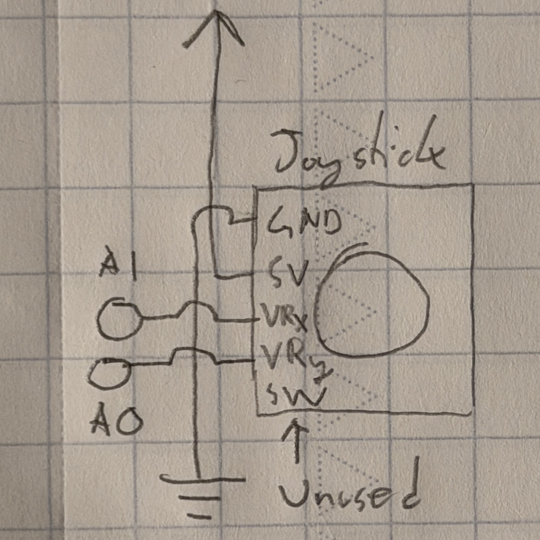
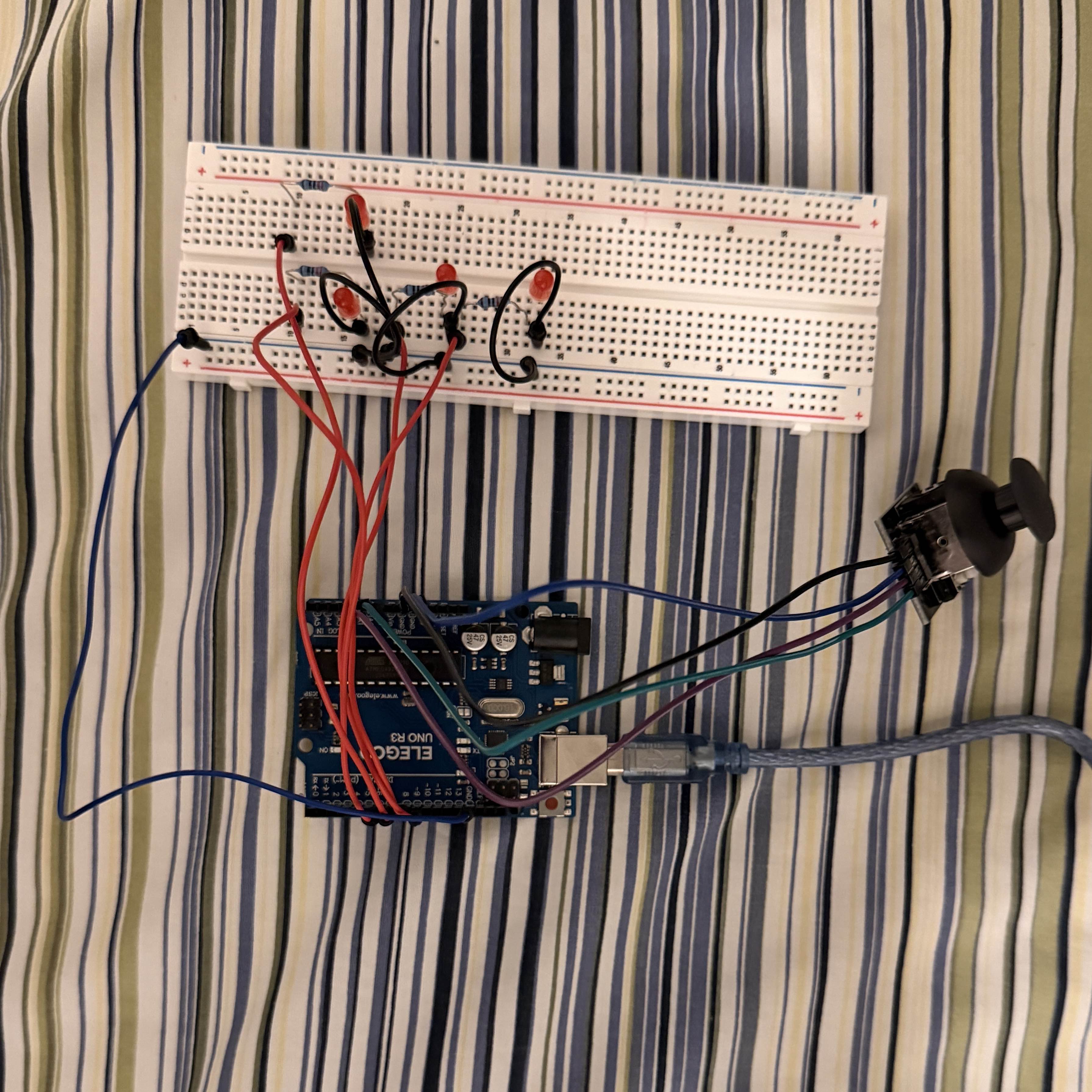 Picture of my circuit. The Arduino receives position data from the joystick and
utilizes that to light up the LEDs based on the stick's current direction. It also
sends/receives data to my computer and the webpage. Up to two LEDs can be lit at once,
based on the joystick directions. I did not use the joystick's SW pin, which is used
by the joystick button.
Picture of my circuit. The Arduino receives position data from the joystick and
utilizes that to light up the LEDs based on the stick's current direction. It also
sends/receives data to my computer and the webpage. Up to two LEDs can be lit at once,
based on the joystick directions. I did not use the joystick's SW pin, which is used
by the joystick button.
These diagrams represent the configuration of the LEDs and joystick. The joystick
included in the class kit has five pins for a 5 V power source and ground, axis
readings, and a button input. As previously mentioned, I didn't use the button input
pin and the axis readings were sent to two of the Arduino's analog pins.
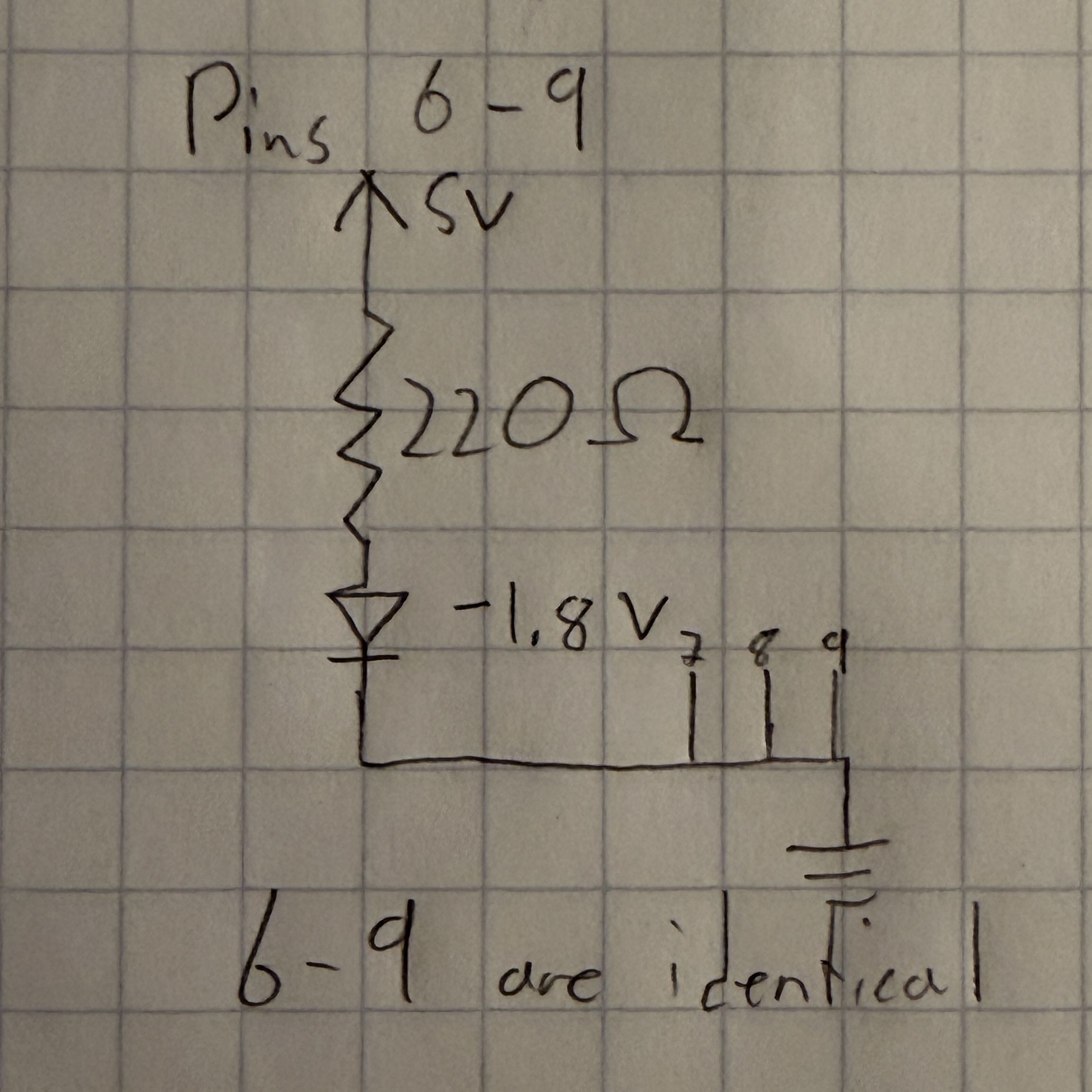
The red LEDs are the same ones used in previous projects this quarter, and draw 5 V
with an ideal maximum current of around 20 mAh. Each LED draws power from a separate
digital pin on the Arduino, which is how they are separately lit up. For each of the
LEDs, I used the following Ohm's law calculation to find ideal resistances:
5V - 1.8V / 20 mA = R = 160 Ω
I chose 220 Ω resistors to get closest to this value.
Code:
This is my code for the Arduino, using inputs from the joystick to control the LEDs
and the webpage objects. It also controls the LED function based on computer input:
    // Controls four LEDs and sends signals to the connected computer through a serial port based on
    // the position of an attached joystick. Toggles the function of the LEDs if a computer key is
    // pressed (with webpage code).
    const int xPin = A1; // Identifies the X-axis pin
    const int yPin = A0; // Identifies the Y-axis pin
    const int ledL = 9; // Identifies the left LED pin
    const int ledR = 8; // Identifies the right LED pin
    const int ledUp = 7; // Identifies the upper LED pin
    const int ledDn = 6; // Identifies the lower LED pin
    int xVal = 0; // Creates a variable for the X-axis reading
    int yVal = 0; // Creates a variable for the Y-axis reading
    int xMax = 0; // Initial maximum X-axis value (0-1023)
    int xMin = 1023; // Initial minimum X-axis value
    int yMax = 0; // Initial maximum Y-axis value
    int yMin = 1023; // Initial minimum Y-axis value
    bool lights = true; // Creates a variable for the lights

    void setup() {
        Serial.begin(9600); // Sets baud rate for serial usage
        while (millis() < 5000) { // Starts calibration period to set up deadzones
            xVal = analogRead(xPin); // Reads the value from the X-axis pin
            yVal = analogRead(yPin); // Reads the value from the Y-axis pin
            if (xVal > xMax) { // If current X-axis reading exceeds the max recorded value
                xMax = xVal; // Sets the max value to the current value
            }
            if (xVal < xMin) { // If current X-axis reading exceeds the min recorded value
                xMin = xVal; // Sets the min value to the current value
            }
            if (yVal > yMax) { // If current Y-axis reading exceeds the max recorded value
                yMax = yVal; // Sets the max value to the current value
            }
            if (yVal < yMin) { // If current Y-axis reading exceeds the min recorded value
                yMin = yVal; // Sets the min value to the current value
            }
        }
        xMax = xMax + 3; // Sets deadzone of 3 units
        xMin = xMin - 3; // Sets deadzone of 3 units
        yMax = yMax + 3; // Sets deadzone of 3 units
        yMin = yMin - 3; // Sets deadzone of 3 units
        pinMode(ledL, OUTPUT); // Sets the left LED pin for output
        pinMode(ledR, OUTPUT); // Sets the right LED pin for output
        pinMode(ledUp, OUTPUT); // Sets the upper LED pin for output
        pinMode(ledDn, OUTPUT); // Sets the lower LED pin for output
    }

    void loop() {
        if (Serial.available() > 0) { // If there is serial output
            int inByte = Serial.read(); // Reads from the port
            if (inByte == 49) { // If "1" was received
                lights = false; // Sets lights to false
            } else { // If lights is not true
                lights = true; // Sets lights to true
            }
        }
        if (lights) { // If lights is true
            xVal = analogRead(xPin); // Reads the value from the X-axis pin
            yVal = analogRead(yPin); // Reads the value from the Y-axis pin
            Serial.print(xVal); // Prints the Y-axis input
            Serial.print(","); // Separates the values
            Serial.println(yVal); // Prints the X-axis input
            if (xVal > xMax) { // Stick pushed right
                digitalWrite(ledR, HIGH); // Turns on right LED
                digitalWrite(ledL, LOW); // Turns off left LED
            } else if (xVal < xMin) { // Stick pushed left
                digitalWrite(ledR, LOW); // Turns off right LED
                digitalWrite(ledL, HIGH); // Turns on left LED
            } else { // Stick in X-axis deadzone
                digitalWrite(ledR, LOW); // Turns off right LED
                digitalWrite(ledL, LOW); // Turns off left LED
            }
            if (yVal > yMax) { // Stick pushed down
                digitalWrite(ledUp, LOW); // Turns off upper LED
                digitalWrite(ledDn, HIGH); // Turns on lower LED
            } else if (yVal < yMin) { // Stick pushed up
                digitalWrite(ledUp, HIGH); // Turns on upper LED
                digitalWrite(ledDn, LOW); // Turns off lower LED
            } else { // Stick in Y-axis deadzone
                digitalWrite(ledUp, LOW); // Turns off upper LED
                digitalWrite(ledDn, LOW); // Turns off lower LED
            }
            delay(50); // Wait 50 ms
        } else { // If lights is not true
                digitalWrite(ledR, LOW); // Turns off right LED
                digitalWrite(ledL, LOW); // Turns off left LED
                digitalWrite(ledUp, LOW); // Turns off upper LED
                digitalWrite(ledDn, LOW); // Turns off lower LED
                return; // Returns
        }
    }
This is my p5.js code, which draws the actual objects on the webpage based on the
Arduino signal. It also sends keypress signals back to the Arduino:
    // Uses data from the Arduino to control a square and circle on the screen, representing the
    // joystick axis positions. Also toggles the function of the LEDs (with Arduino code) when a key
    // is pressed on the computer.
    // This code is partly based on the in-class p5.js demos, although the code for drawing the
    // elements is original.
    const BAUD_RATE = 9600; // Sets up baud rate for serial usage
    let port, connectBtn, elementSize; // Declare global variables

    // Sets up the canvas
    function setup() {
        setupSerial(); // Runs the serial setup function
        createCanvas(windowWidth, windowHeight); // Creates a canvas sized to the browser window
        textFont("system-ui", 50); // Sets the font (https://p5js.org/reference/)
        textStyle(BOLD); // Sets the font style to bold
        textAlign(CENTER, CENTER); // Sets text center alignment
        blendMode(ADD); // Sets canvas blend mode (https://p5js.org/reference/#/p5/blendMode)
    }

    // Creates the visuals
    function draw() {
        const portIsOpen = checkPort(); // Check whether the port is open (see checkPort function below)
        if (!portIsOpen) return; // Returns (exit the loop) if the port isn't open
        let str = port.readUntil("\n"); // Reads from the port until reaching a new line
        if (str.length == 0) return; // Returns if nothing is read
        let positionArray = str.trim().split(","); // Trims whitespace, splits array elements by commas
        elementSize = min(windowWidth, windowHeight) * 0.3; // Limits size of the main elements

        clear(); // Clear the canvas
        background(0); // Make the background black
        translate(windowWidth / 2, windowHeight / 2); // Move the origin to the center

        fill("cornflowerblue"); // Sets color for text/objects
        text(`Joystick position: X${positionArray[0]}, Y${positionArray[1]}`, 0, elementSize + 50); // Text display

        const xPos = round(map(Number(positionArray[0]), 0, 1023, elementSize * -1, elementSize)); // Maps X position
        const yPos = round(map(Number(positionArray[1]), 0, 1023, elementSize * -1, elementSize)); // Maps Y position
        circle(xPos, 0, elementSize / 4); // Draws X-axis circle
        square(0 - elementSize / 8, yPos - elementSize / 8, elementSize / 4); // Draws Y-axis square
    }

    // Writes to the serial port if a key is pressed
    function keyPressed() {
        port.write("1"); // Writes "1" to the port
    }

    // Writes to the serial port if a key is released
    function keyReleased() {
        port.write("0"); // Writes "0" to the port
    }

    // Helper function to set up the serial
    function setupSerial() {
        port = createSerial(); // Sets up the port
        let usedPorts = usedSerialPorts(); // Getting the used ports
        if (usedPorts.length > 0) { // Checks if there are any used ports
            port.open(usedPorts[0], BAUD_RATE); // Opens the first used port
        }
        connectBtn = createButton("Connect to Arduino"); // Creates a connect button
        connectBtn.position(5, 5); // Positions the button in the top left of the screen
        connectBtn.mouseClicked(onConnectButtonClicked); // On click, runs onConnectButtonClicked
    }

    // Changes the button appearance and returns a value based on the status of the port
    function checkPort() {
        if (!port.opened()) { // If the port is not opened
            connectBtn.html("Connect to Arduino"); // Modifies the button text
            background("gray"); // Sets the background color to gray
            return false; // Returns false
        } else { // If the port is opened
            connectBtn.html("Disconnect"); // Modifies the button text
            return true; // Returns true
        }
    }

    // Toggles opening the port when the connect button is clicked
    function onConnectButtonClicked() {
        if (!port.opened()) { // If the port is not opened
            port.open(BAUD_RATE); // Opens the port
        } else { // If the port is opened
            port.close(); // Closes the port
        }
    }
Click to go back to homepage