Left: A servo reacting as I touch the resistor which is serving as a capacitive sensor. It points further to the left when I touch the sensor.
Left: A servo reacting as I touch the resistor which is serving as a capacitive sensor. It points further to the left when I touch the sensor.
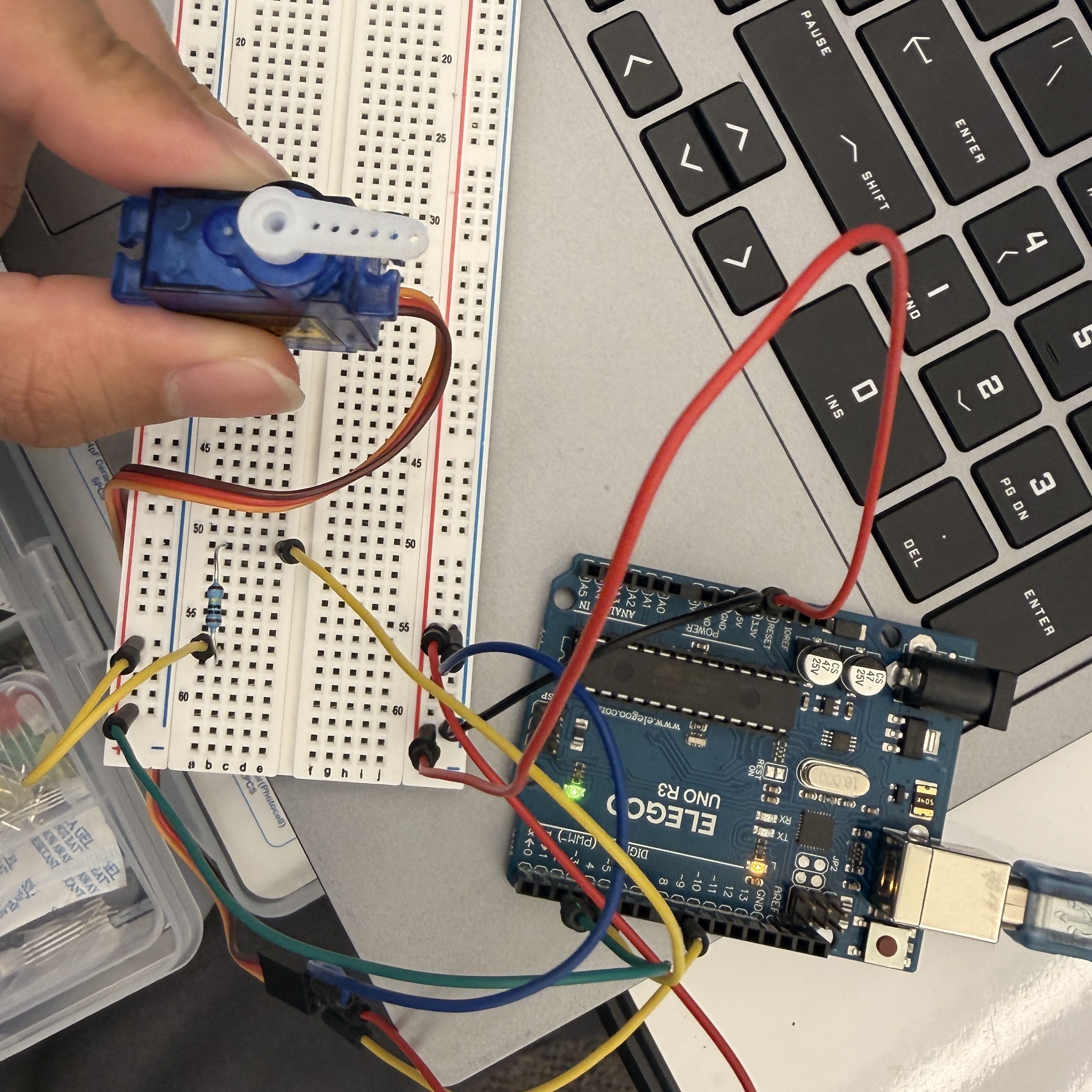 Picture of my circuit. The capacitive sensor is read by the Arduino, which uses its
output to write a position to the servo.
Picture of my circuit. The capacitive sensor is read by the Arduino, which uses its
output to write a position to the servo.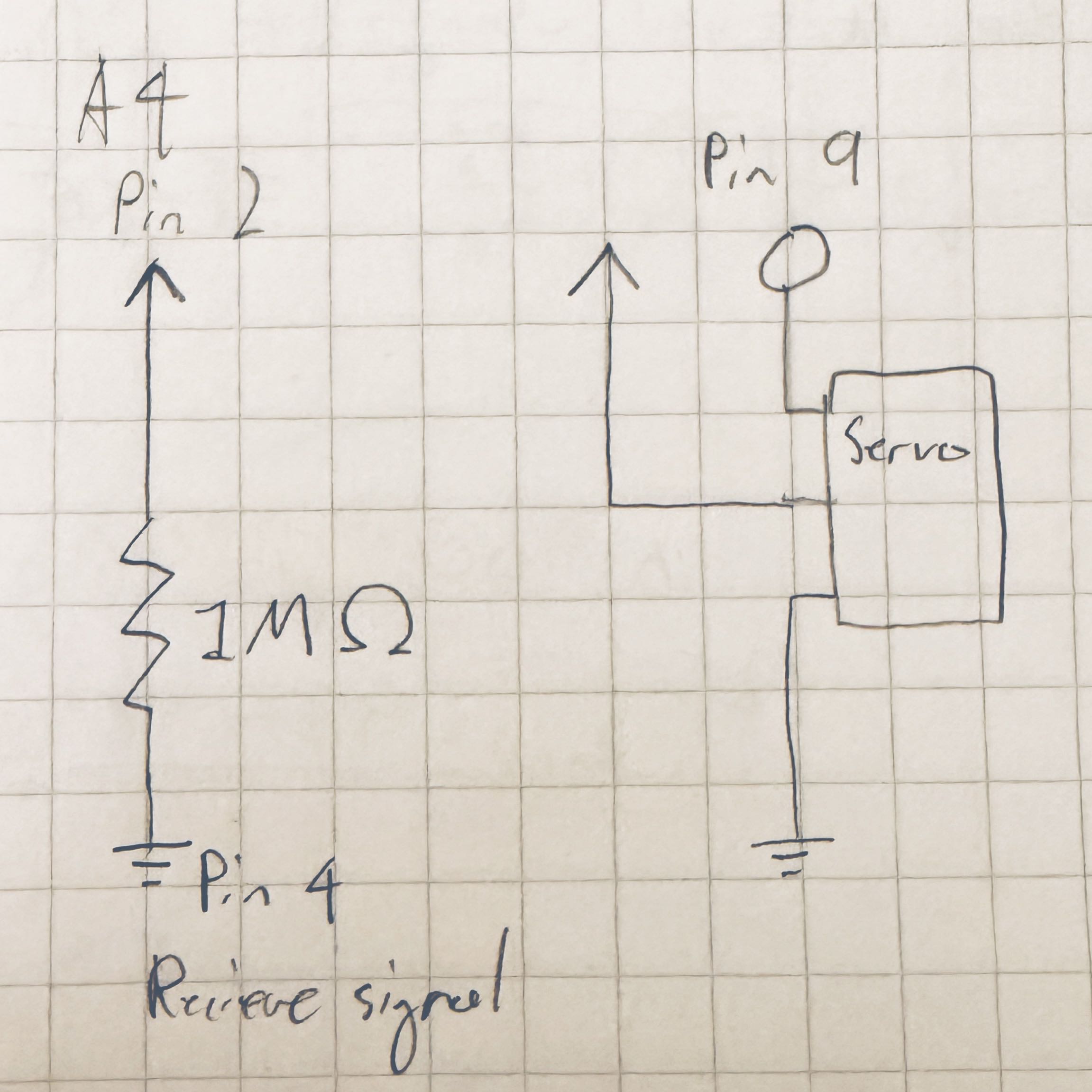 This circuit diagram shows both the capacitive sensor and the servo. The 1M Ω resistance
for for the sensor was chosen based on the library creator's recommendation of 50K-50M Ω
for a resistor. I couldn't find a standardized symbol for a servo so I used a simple box
with the signal, power, and ground.
This circuit diagram shows both the capacitive sensor and the servo. The 1M Ω resistance
for for the sensor was chosen based on the library creator's recommendation of 50K-50M Ω
for a resistor. I couldn't find a standardized symbol for a servo so I used a simple box
with the signal, power, and ground.
        /*
        Uses a servo to indicate signal values from a basic capacitive sensor.
        Uses code from Paul Badger's capacitive sensor demo and the Arduino servo library
        */

        // Note: Carats removed from these lines to allow them to display in HTML
        #include Servo.h // Include servo library
        #include CapacitiveSensor.h // Include capacitive sensor library

        Servo myservo; // Servo object is used to control a specific servo
        int pos = 0; // Variable for storing servo position
        CapacitiveSensor sensor = CapacitiveSensor(4, 2); // Capacitive sensor between pins 4 and 2
        int minVal = 1023; // Initial minimum sensor value
        int maxVal = 0; // Initial max sensor value
        int dataRange = 0; // Initial data range
        int mapVal = 0; // Initial mapped value

        void setup() {
          myservo.attach(9); // Sets up servo to attach to pin 9
          sensor.set_CS_AutocaL_Millis(0xFFFFFFFF); // Turns off automatic calibration
          Serial.begin(9600); // Identifies the serial monitor port
          while (millis() < 5000) { // Starts calibration period
            long calibData = sensor.capacitiveSensor(30); // Sensor output value
            if (calibData > maxVal) { // If current sensor output exceeds the max recorded value
              maxVal = calibData; // Sets the max value to the current output
            }
            if (calibData < minVal) { // If current sensor output exceeds the min recorded value
              minVal = calibData; // Sets the min value to the current output
            }
          }
          dataRange = maxVal - minVal; // Calculates the data range
        }

        void loop() {
          long sensorVal = sensor.capacitiveSensor(30); // Reads value from the sensor
          Serial.print("Original output: "); // Caption for console value
          Serial.print(sensorVal); // Print the original sensor value
          delay(100); // Delays measurements
          mapVal = map(sensorVal, minVal, maxVal, 0, 180); // Maps sensor value to servo position
          Serial.print("\t Mapped output: "); // Caption for mapped values
          Serial.println(mapVal); // Prints mapped value
          myservo.write(mapVal); // Writes mapped value to servo
          delay(5); // Additional delay
        }
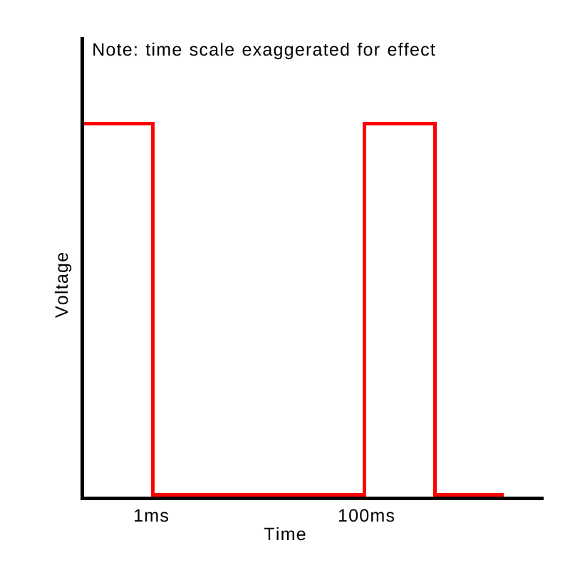 This graph shows a 1ms pulse wave modulation that is rotating the servo once every
100ms period (distances exaggerated for scale).
This graph shows a 1ms pulse wave modulation that is rotating the servo once every
100ms period (distances exaggerated for scale).
2. A possible solution could include mapping inputs to the known correct range. For example,
if a value is outside of a range, map it to be within the range using the map function.
Alternatively, limit values so that it is only recognized as valid if displayed a certain
number of times/for a certain duration, so that the 1% error is discarded.
3. A way to address this could be to average the readings since they deviate higher and lower by an equal amount. For example, over blocks of short time periods average the readings and only utilize the averaged value. With a short period this would allow the readings to stay responsive but also minimize the random deviations.
4. I did not use AI tools while working on this assignment.
Click to go back to homepage